


PT2399 based Delay
Introduction
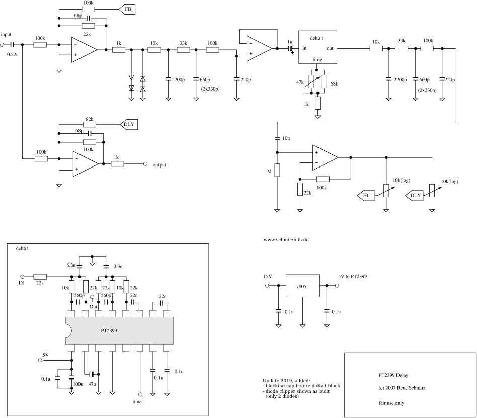
This circuit is my take on a delay unit based on the PT2399 chip.
The circuit
There are only some minor tweaks to the schematic from the datasheet, first of all I lowered the 100nF capacitors in the Delta Encoders and Decoders, this gives the unit a higer bandwidth. So I also had to change the filters to accomodate for that. At longer delay settings the circuit might therefore have somewhat more noise, while at shorter settings it has more bandwidth. Since I didn't like the clipping of the chip, and to make the response more like an analog (tape) delay I added a softclipper before the digital delay core. So the delay allows going softly into selfregeneration, with feedback even stronger than 1. The pots permit setting the amount of regeneration and the relative amplitudes of the dry and delayed signal.
Construction
There are a few unlabelled components in the drawing. Some people have enquired about this. The opamps can be any standard opamps, like TL074, TL084. or similar ones. The diodes are 1N4148, again any small signal diode will do. What I ususally don't show is the power connections. You need to use a symmetric dual supply, like it is generally used in synthesizers. The opamps all run from +15 and -15volts. Although other voltages can also be used, like +-12V. The subcircuit block labelled "delta t" in the upper left should be connected to the part shown in the lower right. Note the three blobs called in, out and time. The like named arrow-labels DLY and FB also need to be connected together.